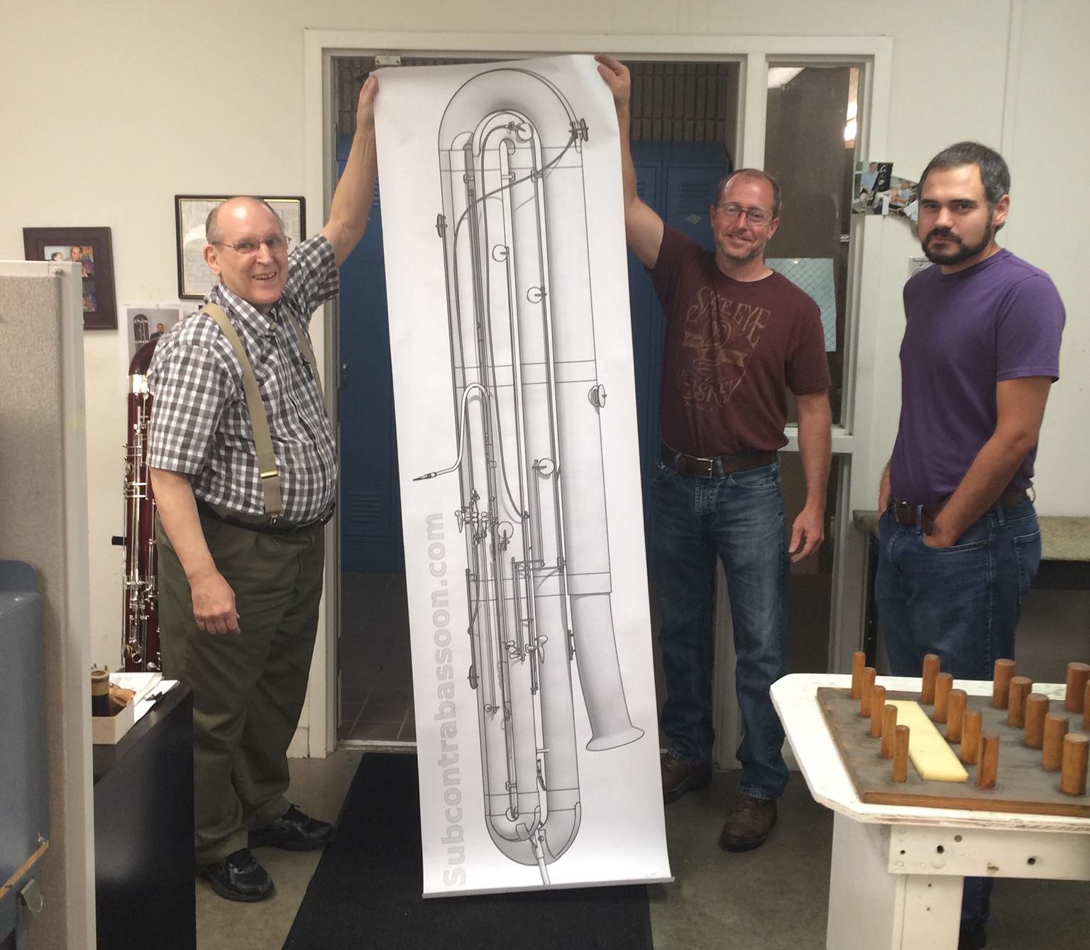
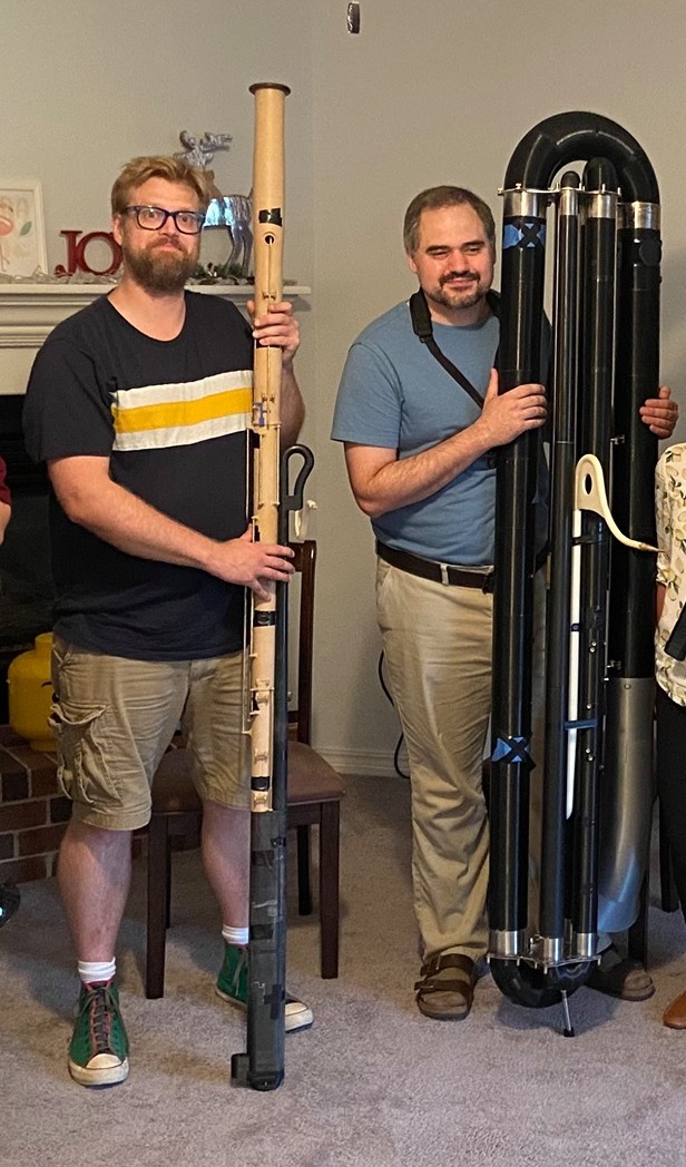
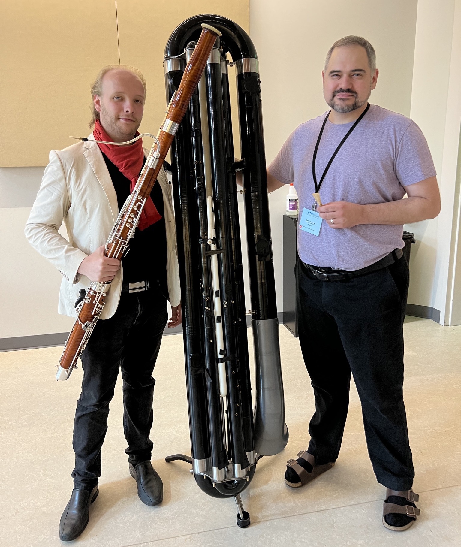
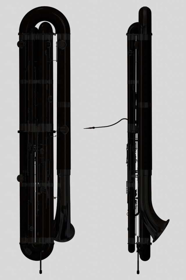
Subcontrabassoon Mk3 Design Explorer
Subcontrabassoon
- one octave lower than contrabassoon
- sounding two octaves lower than written, or written with 15mb clefs
- basic contrabassoon fingering system
- low range: A −1 (13.75 Hz)
- high range: at least F2, ideally D3
- overall height: 191 cm
(6′ 3″)(not including adjustable endpin) - estimated weight of maple version: 17 kg
(38 lbs) - estimated weight of plastic prototype: 24 kg
(53 lbs) - bocal and keywork at approximately same height as on contrabassoon
- (see Other>Prototype for a render of the plastic prototype)
Frame Assembly
- provides primary structural framework for instrument, reducing load on body joints and bends
Support Columns
- bolted between top frame and middle frame, and between middle frame and bottom frame
- relieves body joint tenons from entire burden of securing instrument together
- turnbuckles allow for fine length adjustment to aid in assembly/disassembly and to allow for expansion/contraction of body joints
Top Frame
- sockets for small, wing, upper boot, lower boot, and bass sections
- attachment points for small and boot bends
- stud connections for bell assembly
- bolted to middle frame via support column
Middle Frame
- sockets for small, wing, upper boot, lower boot, and bass sections
- attachment point for tube assembly
- bat'leth handles for easier handling and lifting
- bolted to top and bottom frames via support columns
- six-digit serial number: because one digit would be limiting, two digits presumptuous, and three digits ostentatious, but six digits wraps around to being funny
Bottom Frame & Endpin
- sockets for wing, upper boot, lower boot, and bass sections
- attachment points for wing and bass bends
- bolted to middle frame via support column
- removable endpin receiver
- endpin threaded to prevent risk of slipping
- short 270 mm endpin shown, providing 140 mm
(5½″)of height adjustment - design accommodates an endpin up to 370 mm long, providing 240 mm
(9½″)of height adjustment
Reed
- overall length: 85 mm
- blade length: 43 mm
- tip width: 27 mm
- made from 32–34 mm tube cane gouged to 1.65 mm
- (all dimensions subject to experimentation)
Bocal
A440 length
- 370 mm long
- 5.2 mm
(0.205″)inner diameter at reed end - (due to the more gradual taper and much shorter length relative to the instrument, the large end is actually very slightly smaller that of a bassoon bocal)
Linkages
- unlike Mk2 design (which featured Bowden cables), cumbersome cross-section linkages are accomplished with miniature ball-joint linakges
- F♯, low E, low D, low B♭, and low A keys
Tube/Small Assembly
bocal, tube assembly, and small section
- corrensponds acoustically to the bassoon’s bocal and upper wing joint
- vents for lower octave, upper octave, and high harmonic keys
- C♯, lower octave, and upper octave keys (see Keywork>Left Hand)
- (this assembly alone is roughly the same length as an entire bassoon!)
Tube Assembly
descending tube, tube bend, and ascending tube
- bocal receiver
- vents for upper octave, and high harmonic keys
- C♯, lower octave, and upper octave keys (see Keywork>Left Hand)
Small Section
first joint and second joints
- vent for lower octave key
Wing Section
third, fourth, fifth, and sixth joints
- corresponds acoustically to the lower two-thirds of the bassoon’s wing joint
- toneholes for F♯1, F1, E1, E♭1, D1, C♯1
- “half-hole” vents and automatic mechanism
- majority of lefthand keytouches (see Keywork>Left Hand)
Upper Boot Section
seventh, eighth, ninth, and tenth joints
- roughly corresponds acoustically to the descending half of the bassoon’s boot joint
- toneholes for C1, B0, B♭0, A0, A♭0
- all righthand keytouches (see Keywork>Right Hand)
Lower Boot Section
eleventh, twelfth, thirteenth, and fourteenth joints
- roughly corresponds acoustically to the ascending half of the bassoon’s boot joint
- toneholes for G0, F♯0, F0, and E0
Bass Section
fifteenth, sixteenth, seventeenth, and Owen joints
- roughly corresponds acoustically to the lower two-thirds of the bassoon’s long joint
- toneholes for D0, C♯0, and C0
Bell Section
Newton joint, Rønnes joint, and low A bell
- toneholes for B−1 and B♭−1
Bell Assembly
bell bend and bell section
- roughly corresponds acoustically to bassoon’s bell joint (plus low A extension)
- toneholes for B−1 and B♭−1
- designed to be removed and disassembled for storage and transport
- can be replaced with low C bell to place instrument in low C configuration (see Other>Low C Configuration)
Bends
small, wing, boot, and bass bends
- bolted to top and bottom frames
Tube Bend
- water hole and key
- easily removable for cleaning and drying
- slides over short distance to provide fine tuning adjustment (sufficient to raise to A442 and lower to A439)
Small Bend
- connects bores of small and wing sections
Wing Bend
- connects bores of wing and upper boot sections
Boot Bend
- connects bores of upper boot and lower boot sections
- (the G0 tonehole, which was located on the boot bend on the Mk2, has been relocated to the lower boot section for improved tuning and easier manufacture)
Bass Bend
- tonehole for E♭0
- connects bores of lower boot and bass sections
Bell Bend
- socket for bell section
- connects bores of bass and bell sections
Low C Bell
- attached to top frame in lieu of bell assembly
Low C Configuration

- when notes below C0 are not required, bell assembly can be replaced with low C bell for reduced bulk
- overall height reduced to 183 cm
(6′ 0″)(not including adjustable endpin)
Γ Valve

- Perhaps surprisingly, the word “gamut” originated in music theory as a contraction of “gamma-ut”, the expected full range of notes from low G up to high C. It would thus seem historically fitting to return G to its rightful place as the lowest note by extending the subcontrabassoon even further to G−1.
- However, adding 1.4 m of conical bore to the end of an already gigantic instrument would be unworkable. Likely the only viable solution would be a replacement for the tube bend, which would add a long length of cylindrical tubing controlled by a bass trombone rotor valve. By activating this valve, low B♭ could be lowered to a slightly flat A♭−1, and low A could be lowered to a slightly sharp G−1.
- The limitations would be probable instability due to the disrupted bore taper, difficulty in sealing the rotor well enough to support the fundamental register of a woodwind instrument, and the complete and utter lack of musical justification.
- As low A already requires the use of all 10 digits, operation of the Γ valve would need to be controlled via a foot pedal. Probably for the best that it remain hypothetical.
- If the concept could be made workable, it would probably be more valuable as a lightweight and compact solution for producing low B♭ and low B while in low C configuration.
Altissimo Vent

- The Mk2 prototype, with the planned standard vents, is able to sound all the way up to E♭3. This provides the subcontrabassoon a more-than-adequate range virtually identical to the standard ranges for bassoon and contrabassoon.
- To reliably play any higher, the subcontrabassoon would need an additional altissimo vent on the bocal, similar to those on the contraforte.
- As hilarious as the notion of a 32′ instrument playing in the flute range is, this will likely remain no more than a notion.
Mk2 vs. Mk3
- (The legacy Mk2 Design Explorer can be found here)
Form Factor Differences
- Overall, the Mk3 design has almost the same form factor as the Mk2. The body sections are 40 mm
(1½″)shorter. However, the bell bend is slightly taller, resulting in the whole instrument being only 13 mm(½″)shorter. - Each of the main body sections is divided into four joints, rather than three. This allows an addition of a middle frame, which will reduce flexing in the middle of the sections, as well as providing a mounting point for the descending tube. The middle frame also includes lifting handles.
- The ascending tube now extends only to the middle frame, rather than all the way to the top frame. A new “small section” connects the ascending tube to the small bend.
- The tube bend slide has been shortened, to allow for better placement of harmonic vents at the sacrifice of tuning range.
- Bocal has been shortened significantly for easier manufacture; 370 mm
(14½″)rather than 500 mm(19½″). The descending and ascending tubes have been accordingly lengthened to make up the difference.
Tonehole Differences
- All toneholes have been tweaked for improved intonation, based upon tuning tests conducted on the Mk2 prototype.
- The G0 tonehole has been relocated from the boot bend to the lower boot section, for improved intonation and easier manufacture.
- The Mk2 design tentatively featured a single “half-hole” vent and doubled vents for the lower octave and upper octave keys. Experimentation on the Mk2 prototype determined that the situation should be reversed; doubled “half-hole” vents and single vents for the lower octave and upper octave keys.
- The original “third harmonic key” is repositioned much higher up the instrument, after experimentation showed it was not necessary below B♭2. It is now called the “high harmonic key” and works up to E♭3.
Keywork Differences
- The Mk2's bowden cable linkages have been replaced with miniature ball joint linkages, for more reliable sealing of open-sprung keys and reduced maintenance needs.
- The B♭ and F♯ keytouches have been modified to allow for slurs between these notes without the need for front F♯ or front B♭ keys.
- The e/f♯ trill key, alternate E♭ key, and high harmonic key will now be considered as standard. The alternate E♭ key has been placed for the right thumb (above the B♭ key), and the high harmonic key has been relocated to a palm key for the right hand.
- At present, the only “alternate” keys are the right thumb E♭ key and the alternate upper octave keytouch. The design could accommodate a right thumb A♭ key, but the lack of a front F♯ key renders it of dubious utility.
High Range
- Like the contrabassoon, all of the subcontrabassoon's harmonic vents are completely independent of one another. While this may seem inconvenient, this allows the vents to be activated in combinations that would be impossible with a fully-automatic system. On the Mk2 prototype, the following combinations were found to work:
- Using the upper octave vent with the “half-hole” mechanism, the notes F♯2 and G2 can be produced as third harmonics.
- Using the lower octave vent with the “half-hole” mechanism, the notes G♯2 and A2 can be produced as third harmonics.
- Using the high harmonic vent with the lower octave vent, the notes A♯2, B2, and C3 can be produced as third harmonics.
- Using the high harmonic vent with the “half-hole” mechanism, the notes C♯3, D3, and E♭3 can be produced as fourth harmonics.
- Using the high harmonic vent alone, the notes E3 and F3 were inconsistently produced as fifth harmonics. Further experimentation may yield better fingerings.
Left-Hand Keywork
- Fingers
- LH1: E/F key, e/f♯ trill
- LH2: D/E key, E♭ key
- LH3: C/D key
- LH4: low E♭ key, low C♯ key, low A key
- Thumb
- low D key, low C key, low B key, low B♭ key
- C♯ key, lower octave key, upper octave key
- alternate keytouch for upper octave key
Right-Hand Keywork
- Fingers
- RH1: B/C key
- RH2: A/B key
- RH3: G/A key
- RH4: low F key, A♭ key
- Thumb
- B♭ key, low E key, F♯ key
- (modified shape of B♭ and F♯ keytouches allows for slurs without the need for alternate keys)
- alternate E♭ key
- Palm
- high harmonic key
Prototype
- The subcontrabassoon is designed so that one could be made from wood using traditional methods, though the prototype itself will have body joints made of ASA plastic
- While the Mk2 prototype body joints were 3d-printed in segments and glued together (due to the build limits of an off-the-shelf printer), a custom-built 3D-printer has allowed the Mk3 straight body joints to be printed in single pieces; only the bell and bends require gluing
Lineart
- <marge_simpson_with_potato.gif>
Case
- For easier transportation and flexible performance options, the subcontrabassoon will be divided into two separate cases
- Case #1
- 190 cm × 38 cm × 30 cm
(74″ × 15″ × 12″) - Contains majority of the instrument, in one assembled piece
- Also includes bocal, tube bend, and low C bell
- Case #2
- 79 cm × 38 cm × 30 cm
(31″ × 15″ × 12″) - Contains low A bell assembly, disassembled into four pieces
- Unnecessary when instrument is to be played in low C configuration
- For comparison, a typical contrabassoon case is 137 cm × 36 cm × 20 cm
(54″ × 14″ × 8″)
[Unnamed] Joint
first joint / first joint of small section
- lower octave vent, positioned to produce the second harmonics of A0 through C♯1
[Unnamed] Joint
second joint / second joint of small section
[Unnamed] Joint
third joint / first joint of wing section
- tonehole for F♯1 (e/f♯ trill key)
- two coupled “half-hole” harmonic vents, positioned to produce the second harmonics of F♯1, G1, and A♭1
[Unnamed] Joint
fourth joint / second joint of wing section
- toneholes for E1 and F1
- automatic mechanism to open “half-hole” vents whenever LH2 is depressed but LH1 is not
- (unlike contrabassoon, “half-hole” vents remain closed for open F)
[Unnamed] Joint
fifth joint / third joint of wing section
- tonehole for E♭1
- majority of left hand keytouches (see Keywork>Left Hand)
- left handrest
[Unnamed] Joint
sixth joint / fourth joint of wing section
- toneholes for C♯1 and D1
[Unnamed] Joint
seventh joint / first joint of upper boot section
- toneholes for B0 and C1
- majority of right hand keytouches (see Keywork>Right Hand)
- right handrest
[Unnamed] Joint
eighth joint / second joint of upper boot section
- tonehole for B♭0
- keytouches for alternate E♭ and high harmonic keys (see Keywork>Right Hand)
[Unnamed] Joint
ninth joint / third joint of upper boot section
- tonehole for A0
[Unnamed] Joint
tenth joint / fourth joint of upper boot section
- tonehole for A♭0
[Unnamed] Joint
eleventh joint / first joint of lower boot section
- tonehole for G0
[Unnamed] Joint
twlefth joint / second joint of lower boot section
- tonehole for F♯0
- low F/F♯ linkage
[Unnamed] Joint
twlefth joint / third joint of lower boot section
- tonehole for F0
[Unnamed] Joint
fourteenth joint / fourth joint of lower boot section
- tonehole for E0
[Unnamed] Joint
fifteenth joint / first joint of bass section
- (the tonehole for E♭0 is located on the bass bend (see Bends>Bass Bend) )
[Unnamed] Joint
sixteenth joint / second joint of bass section
- tonehole for D0
[Unnamed] Joint
seventeenth joint / third joint of bass section
- tonehole for C♯0
Owen Joint
eighteenth joint / fourth joint of bass section
- tonehole for C0
- named for the late Chip Owen, contrabassoon guru at Fox and an extraordinarily generous source of advice and inspiration for the subcontrabassoon project

Newton Joint
nineteenth joint / first joint of bell section
- tonehole for B−1
- named for Bret Newton, one of the earliest and most enthusiastic supporters of the instrument

Rønnes Joint
twentieth joint / second joint of bell section
- tonehole for B♭−1
- Named for the Rønnes family, among the earliest and most enthusiastic supporters of the instrument

Bell

- metal bell preferred, for reduced weight (prototype will use plastic bell)
- (slightly larger than a baritone saxophone bell)
Descending Tube
- tube bend inner receiver
- upper octave vent, positioned to produce the second harmonics of D1 through F1
- high harmonic vent, positioned to aid in the production of notes above A2 (see Keywork>High Range)
- keytouches for C#, lower octave, and upper octave keys (see Keywork>Left Hand)
Ascending Tube
- tube bend inner receiver

View Selection


loading...

Copyright 2024 - Richard S. Bobo
all images simulated


